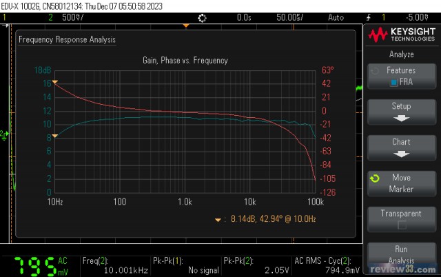
- #68 [johnnykmtang], 23-12-08 22:15Frequency response analysis
- #67 [johnnykmtang], 23-12-08 22:14FFT

- #66 [johnnykmtang], 23-12-08 22:10ECC88 differential balance push pull line amp with use of LL1689AM PP transformer.
The project is done. The power supply employs CCS - Shunt Regulator too. The ECC88 differential amp employs in simple LM317 as constant current source for 10mA. The LL1689AM PP is configured for (9+9) : 4.
I had the ECC88 replaced with 6N6P. After the change, a RC (37.5K 0.001uF) network need to be connected to the secondary of the transformer to damp the resonance at around 80KHz.
To my surprise, this PP style line amp sounds nice to me. I ran the spectrum analysis and the result was excellent. The harmonics are well below the -80dB noise level.
I have been thinking using this circuit to drive any power tube in SE or PP by changing the inter-stage transformer to a (1+1) : (1+1). It would have sufficient driving voltage working as driver for power tubes.
Johnny -
- #65 [johnnykmtang], 23-12-01 22:08People has been criticizing PP circuit sounds sharp and irritating. In fact, I found this 6DJ8 balanced LL1689 PP line amp sounds smooth like silk, lively and dynamic.
By the way, I first thought using the Monolith PP Interstage transformer but I got the second hand LL1689 PP interstage with very good price.
Cheers, enjoy the music.
Johnny - #64 [johnnykmtang], 23-12-01 05:536DJ8 differential push pull with line output transformer

- #63 [johnnykmtang], 23-12-01 05:526DJ8 differential push pull with line output transformer

- #62 [johnnykmtang], 23-12-01 05:486DJ8 differential push pull with line output transformer
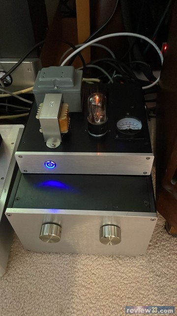
- #61 [johnnykmtang], 23-12-01 05:456DJ8 differential push pull with line output transformer
It is completed assembling and testing this morning. To my surprise, the frequency response is almost flat without any peaks at high frequency end. The secondary of the line transformer is without any load at all.
The external power supply comprises of a CCS using one DN2540 MOSFET to provide 30~50mA.
A shunt regulator module is installed in the amplifier section for B+ filtering and keeping the B+ at 135Vdc.
The FFT spectrum shows the harmonics are very low.
- #60 [niceday009], 23-11-25 18:52Hi Johhny, sent you the email and you might want to contribute in the forum thread 單端胆機同好會
I am in the process of designing the ultimate single 845 integrated amp, why integrated?It is because I always think that the 1st stage(preamp stage)to directly couple the 2nd stage is the edge of amplification design which can exceed the pre power amp combo. The shortest signal distance and elimination of another coupling cap is certainly an advantage.
The target weight of the integrated 845 amp is around 40kg.
At first I used ixys plate CCS on ECC99, but finally I utilized cathode degeneration for distortion reduction
CCS provide more dynamic while simple resistor loaded(with cathode degeneration)make the tone more smooth.
In this integrated 845 amp, I also design my interstage and output tranny in Double C core configuration. The target is to produce 29W A1 and 44W A2 through a single 845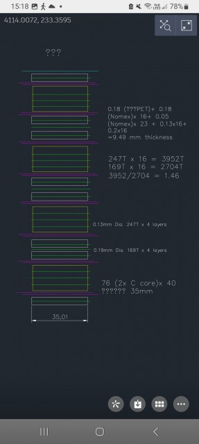
最後修改時間: 2023-11-25 19:05:54 - #59 [johnnykmtang], 23-11-24 21:44My 845 single ended power amplifier back on stage. So good for warming the room during the cold days. The driver tube is 5A/152g in triode mode using CCS for plate load. Both driver and 845 tubes are using shunt regulator in the cathode.

最後修改時間: 2023-11-24 21:49:22 - #58 [johnnykmtang], 23-11-22 04:02Hey Daniel,
Haven't got your email so far.
Johnny - #57 [danielyk8], 23-11-21 00:11Hi Johnny, please check your email. Regards Daniel
- #56 [johnnykmtang], 23-11-20 21:51Quote the following from LARS company website of their design philosophy.
----------------------------------------
Purity is what defines our sound. Research has shown that slight impurities in reproduced music – what scientists call 'grey sound' – irritate the mind and cause stress and fatigue. Using unbalanced circuits or less-than-linear amplification devices is where grey sound begins.
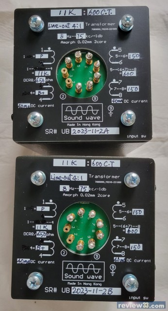
The best way to eliminate grey sound is to design a balanced circuit with a linear construction. All components are then carefully selected to support this linear process, like our silver-plated wiring and solder. We use zero negative feedback and distortion in our amplifiers, and listeners tell us there is an instinctive rightness to our sound. - #55 [wcw12], 23-11-20 12:03有認識這個前級output 牛嗎?
- #54 [johnnykmtang], 23-11-20 09:46http://www.emissionlabs.com/datasheets/SOFIA/EML20B-curves-printversion.pdf
For B+ of 250Vdc, the bias voltage is about 4V and the idle current is 16mA.
The plate resistance is 5K.
Johnny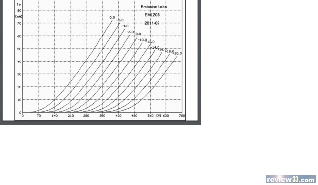
- #53 [johnnykmtang], 23-11-20 09:27
- #52 [johnnykmtang], 23-11-20 07:16Hello danielyk8,
Thank you for sharing the schematic of the EML-20B with LL1689 18mA output transformer. There are few things I want to say.
1. I can't find the datasheet of the EML-20B tube. Therefore, I don't the the plate resistance of the tube to see whether it matches with the source impedance of the LL1689.
2. I would leave the loading at the secondary winding as 100K which is from the power amplifier input. Therefore, you may leave the winding connected to the RCA and XLR connector without the volume pot.
3. RC damping is required to damp the resonance of the LL1689 at high frequency at around 30K. You may use a 2000pF capacitor with a 50K potentiometer to find out the flat frequency to the high end.
4. Using an adjustable shunt regulator at the cathode may improve the sound with better clarity. Also, you can adjust the idle current and THD as needed.
5. I prefer having higher output with LL1689 in 9+9 : 2+2 configuration.
Regards,
Johnny - #51 [danielyk8], 23-11-19 21:25#50, Hi johnny, hope you well. I'm rebuilding my friend's EML 20b with LL1689 am, circuit as follow:

最後修改時間: 2023-11-19 21:27:53 - #50 [johnnykmtang], 23-11-18 21:54I got a pair of Lundahl LL1689 (9+9 : 2+2) amorphous core line output transformer. I plan to build a ECC88/6DJ8 differential line amp with it. I ran a frequency response test of this transformer with 4K source impedance. The -3dB points are about 20Hz and 40Khz which should be fine.
Johnny - #49 [johnnykmtang], 23-11-15 03:01wcw12,
The red spot shows large amount of current flowing through that part of the conductor. That spot is just like a bottle neck. - 下一頁 (1 of 4)
- 返回 ...
